Voith highly flexible couplings shift resonance frequencies in a driveline below idle speed. They also dampen critical torsional vibration amplitudes and shock loads.
Manufacturers and operators have big expectations regarding the productivity of their vehicles and systems: high reliability and short downtimes together with a low total cost of ownership.
Highly flexible couplings from Voith are specially developed for these requirements. They protect the driveline and thus extend the lifetime and availability of all connected drive components. In this way, they increase the productivity of the vehicle or system.
More than 45 years of experience in perfecting drive systems that are subject to torsional vibrations are the foundation on which the relationship with our customers is built.
Customer benefits
Increased availability of all components in the driveline
due to damping of torsional vibrations and shock loads in the driveline
Decreased life cycle costs
due to increased lifetime of all driveline components
Increased comfort
due to less vibration and noise
Our product portfolio
Our products improve the availability of all drive components and thus reduce life cycle costs for the system. The transmitted torques range up to 1300 kNm.
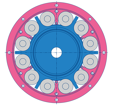
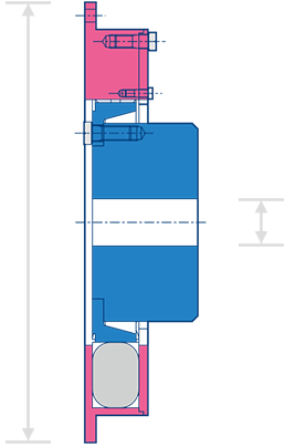
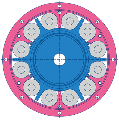
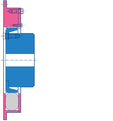
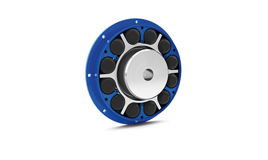
K Couplings are the standard for our highly flexible couplings. They feature a modular design and can be integrated into your drive system with a high degree of flexibility. This makes this type of coupling an ideal and cost-effective choice for many applications in a wide range of industrial sectors.
K Couplings dampen torsional vibrations and shift the natural frequency of the system below idle speed. In addition, K Couplings balance axial, radial, and angular displacements. The operational stability and service life of your machine or your vehicle are increased, which in turn increases availability and reduces life cycle costs.
Outrigger-bearing models and models with torsional limiting device are optional.
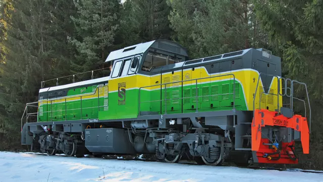
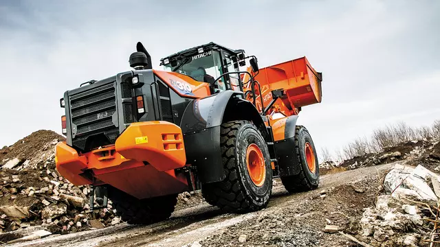
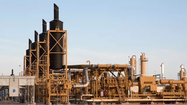
Typical applications: rail vehicles, construction vehicles, engine test rigs, natural gas compressor stations, general industry
Resonance speeds are shifted into non-critical speed ranges. The system runs quieter, increasing comfort when operating the machine or vehicle.
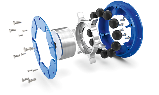
Elastomer elements dampen torsional vibration peaks that occur in the driveline. Thanks to their elasticity, these elements reduce the stresses on the driveline caused by internal combustion engines or load-side units with their natural fluctuations in torque. Your machine or vehicle runs with a high degree of operational durability. And that increases productivity.
The coupling takes the load off all of the drive components, increasing their service life and reducing maintenance costs. The net result is a positive impact on the total cost of ownership for your machine or vehicle – not to mention preventing consequential expenses arising from downtime.
Its modularity makes this coupling extremely flexible with respect to function and design. You get a coupling that is precisely matched to your driveline's technical and design requirements. Standardized components ensure an optimal cost/benefit ratio.
The K Coupling features a high torque capacity. You save installation space while at the same time transferring high torque safely and reliably.
Highly flexible H Couplings are especially well suited for construction machines with a torque converter gearbox with lock-up-clutch, as well as drivelines with a pump splitter gearbox. These couplings feature a spring-mass system and a viscous-hydraulic damping system. They are very compact, temperature-resistant, and highly versatile.
H Couplings dampen torsional vibrations and shock loads in the driveline. The operational stability and service life of your vehicle is increased, which in turn increases the availability and reduces the total cost of ownership.
The viscous-hydraulic damping system operates using a temperature-resistant damping grease. The damping effect increases proportionally to the coupling's angle of twist. This means that severe torsional vibrations, such as those which occur when turning a motor on and off or during load surges, also lead to a greater damping effect. This gives the coupling optimal damping behavior across the entire nominal speed range.
During operating condition the isolation system of the H Coupling becomes active: within the defined backlash range of the damping ring, vibrations are absorbed and isolated. As a resulted, optimum vibration isolation is ensured even in the lower operating speed range.
Resonance speeds are shifted into non-critical speed ranges. The system runs quieter, increasing comfort when operating the equipment or vehicle.
Radially arranged steel compression springs transfer the torque from the motor to the driven machine. The springs operate virtually wear-free and the coupling features very long uptimes. This keeps your service and maintenance costs low.
The damping effect of the coupling remains constant over a very wide range of temperatures. Wide fluctuations in temperature have almost no effect on the operation of the coupling, which means your system or vehicle operates more safely even under extreme environmental conditions.
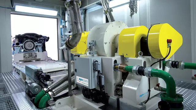
Highly flexible D Couplings are the standard for engine test rigs for testing 1 to 3-cylinder internal combustion engines. D couplings feature a high torsional flexibility and high torque capacity. Development test rigs, continuous-running test rigs, and end-of-line test rigs operate safely and reliably with this coupling at speeds of up to 10,000 rpm.
D Couplings shift a system's critical resonance frequencies below idle speed. In addition, the couplings dampen undesirable alternating torques. This increases the service life of all the test rig drive components. Your test rig operates with a high level of availability.
The D Coupling's modular design enables very flexible integration into a wide variety of engine test rigs. We adapt the length of the coupling, connections, and torsional rigidity to your test rig.
D Couplings feature high torsional flexibility. This makes it possible to reproduce test cycles more precisely in supercritical operation and to achieve particularly precise test results.
A built-in spherical joint ensures balance between the engine and the power take-off. This test rig coupling is suited for engine speeds of up to 10 000 rpm. High-speed engines can be tested up to their maximum speed in most cases.
The coupling's modular design makes it easy to integrate into a wide variety of engine test rigs. The connections can be adapted to almost all types of engines and dynos. This saves on adaptation expenses and allows you to build a better design with a shorter lever arm.
All connected components are relieved when moving through the resonance speed (engine start) and in other speed ranges. This extends the service life of all the test rig driveline components. Higher availability and lower total cost of ownership for your system increase your profits.
Flexible CT Couplings are especially well suited for industrial uses. This type of coupling is virtually failure-free and is an optimal and cost-effective solution for many applications. Elastomer elements under pressure provide a damping effect.
CT Couplings dampen torsional vibrations and shock loads in the driveline. In addition, the coupling balances axial and radial displacements. This increases the operational stability and service life of your equipment or system, which in turn increases the vailability and reduces the total cost of ownership.
Models with plug-in connection for bell-house installation are optional.
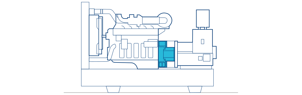
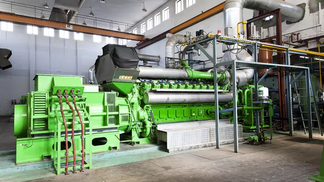
Typical applications: generator sets, crusher, mills, shredders, general industry
The coupling works without creating backlash forces to the system. This increases safety and the availability of all connected components. The net result is a positive impact on the total cost of ownership for your equipment or system – not to mention reducing downtimes and associated costs.
The CT Coupling design makes it virtually failure-free. In the highly unlikely event of damage of the elastomer elements, the coupling will continue to transmit torque. Only the coupling's damping characteristics are affected. You have the option of emergency operation of your equipment or system. This prevents sudden stoppages.
Resonance frequencies are shifted into non-critical speed ranges. The system runs quieter, increasing comfort when operating the equipment or system.
The coupling is virtually maintenance-free and requires no lubrication. The elastomer elements are the only parts subject to natural wear. Replacing the elements is very simple since the coupling consists of only three main components. This helps reduce downtimes and associated costs. Lower maintenance costs optimize your life cycle costs.
The HP Coupling was specifically designed for realistic test scenarios of combustion engines where a dummy gearbox is bell-house-mounted to the engine. In these scenarios, the HP Coupling protects the test rig against damaging torsional vibrations and shifts the natural frequency below idle speed. A viscous-hydraulic damping system and an isolation function give the coupling optimal damping behavior across the entire nominal speed range.
The visco-hydraulic damping of the HP Coupling increases the damping effect in proportion to the coupling’s angle of twist. Severe torsional vibrations, such as those occurring in typical test scenarios, also lead to high damping in this case. During low torsional vibration, the HP Coupling operates in the isolation range where the damping ring absorbs and isolates vibrations within the defined backlash range. This is the decisive benefit over arc spring couplings: it keeps the power loss of the test rig at a minimum and allows very precise test results.
The viscous-hydraulic damping and the isolation function give the coupling optimal damping behaviour across the entire nominal speed range. The power loss is reduced to a minimum and test results are more precise.
A special temperature-resistant PEEK material increases the spring assemblies’ resistance to wear, temperature and strength at high speed. This allows close to real life testing of the engine up to 8 500 rpm.
Critical resonance frequencies of the system are shifted below the idle speed and undesired alternating torques are dampened. This increases the service life of all drive components of the test rig.
The internal steel springs allow a multi-stage stiffness characteristic and are available in 16 different stiffness values. Consequently, the coupling can be finely adjusted to the requirements of the customer.
The damping grease is designed for high speeds and the associated temperatures, ensuring reliable operation of the coupling up to a temperature of 150°C. The optimized lubricant provides the damping that reduces alternating torques in the drive train to a minimum.
Find the right product for your generator set in a few simple steps
Flexible CT-H couplings transfer power safely and are ideally suited for generator sets where space is limited and the generator is connected directly to the engine housing.
Unfortunately, the data submitted falls outside normal specifications.
We value your business and ask that you contact us for a customized solution.
Your solution
CT-H.
CT-H couplings are specifically designed for generator sets where the generator is bell-house mounted to the engine. This coupling type is resistant to high temperatures of up to 130°C and have a blind-assembly feature.
Flexible CT Couplings are especially well suited for industrial uses. This type of coupling is virtually failure-free and is an optimal and cost-effective solution for many applications. Elastomer elements under pressure provide a damping effect.
CT Couplings dampen torsional vibrations and shock loads in the driveline. In addition, the coupling balances axial and radial displacements. This increases the operational stability and service life of your equipment or system, which in turn increases the vailability and reduces the total cost of ownership.
Models with plug-in connection for bell-house installation are optional.
Typical applications: generator sets, crusher, mills, shredders, general industry
The coupling works without creating backlash forces to the system. This increases safety and the availability of all connected components. The net result is a positive impact on the total cost of ownership for your equipment or system – not to mention reducing downtimes and associated costs.
The CT Coupling design makes it virtually failure-free. In the highly unlikely event of damage of the elastomer elements, the coupling will continue to transmit torque. Only the coupling's damping characteristics are affected. You have the option of emergency operation of your equipment or system. This prevents sudden stoppages.
Resonance frequencies are shifted into non-critical speed ranges. The system runs quieter, increasing comfort when operating the equipment or system.
The coupling is virtually maintenance-free and requires no lubrication. The elastomer elements are the only parts subject to natural wear. Replacing the elements is very simple since the coupling consists of only three main components. This helps reduce downtimes and associated costs. Lower maintenance costs optimize your life cycle costs.
Generator sets with a diesel / Gas combustion engine
Oil & gas industry
Reciprocating compressor sets
Pump sets
Crusher, Mills and Shredders
Stationary crushers
Stationary mills
Stationary shredders
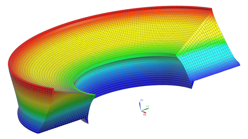
Marine
Containerships
Tugboats
Pleasure boats / Yachts
LNG carriers
Cruise ships
Offshore supply vessels
Technical information
The individual components of a driveline are made of elastic materials (e.g., steel) and have a mass. Accordingly, they represent a system susceptible to torsional vibration. If this system is incited, it will start vibrating with a determined frequency – its natural frequency and amplitude.
If a highly flexible coupling is installed, the vibration amplitude will become a finite value. A reciprocating diesel engine does not convey its power evenly over one rotation of the crankshaft. That is why a diesel engine puts a heavy load on the drive train.
This is amplified by the new injection technologies with very high injection pressures, which have been introduced in the recent years. Additionally, there is a trend toward downsizing of engines, which means fewer cylinders, lighter mass inertia and even higher injection pressure.
A driveline will normally consist of:
The driving machine (prime mover)
Coupling elements (couplings, gears, etc.)
The driven machine (power consumer)
A useful operational strength and unit lifetime is often achieved only after a highly flexible coupling has been installed in the driveline.
All drivelines can be divided into one of the three methods of installation:
Remote-mounted arrangement
Driver and driven machines are installed on different foundations and located relatively distant from each other.
The bearing that guides the joint shaft is integrated into the coupling design.
The weight of the joint shaft and coupling is transmitted to the rear crankshaft bearing.
Depending on the coupling series, friction or antifriction bearings are used.
The friction bearings follow any relative twist of the coupling performing an oscillating rotary movement. This increases the damping factor of the coupling.
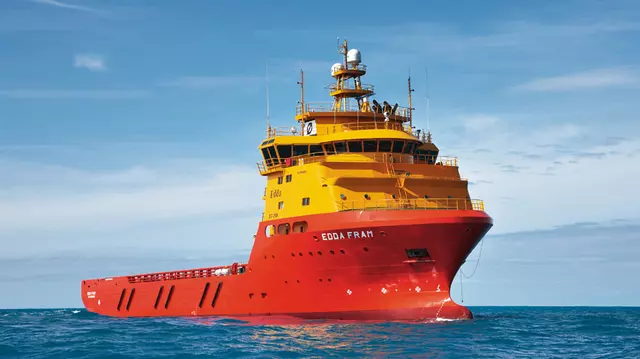
Separate-mounted arrangement
Driver and driven machines are installed on different foundations and located relatively close to each other.
Driver and driven machines have elastic supports and can therefore vibrate in the axial, radial and angular direction relative to one another.
The coupling compensates for these movements by having universal flexibility in axial, radial and angular direction.
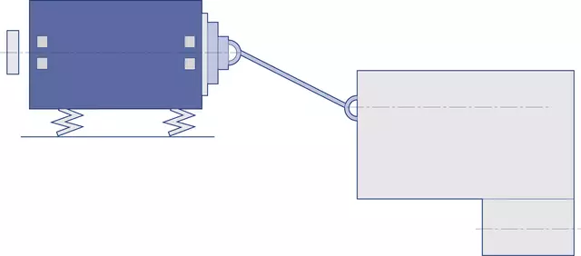
Bell-house-mounted arrangement
The driven machine is directly flanged onto the engine flywheel housing.
The highly flexible coupling is designed as a blind assembly unit since it needs to be mounted at the same time as the driver and driven machine are bolted together.
Engineering services
We supply not only products, but ideas too. Benefit from our many years of experience in all aspects of driveline project planning: