Actuators and control systems for turbomachinery

Actuators and control systems for turbomachinery

Produce safely and efficiently

Steam turbines, gas turbines and compressors achieve exceptional efficiency and operational reliability when using actuators, protection equipment and control systems from Voith.

Get in contact with us Webshop Service
  • Actuators and control systems for Voith turbomachinery

    Actuators and control systems for turbomachinery

    Product brochure PDF, 2.76 MB
    English German

Our product portfolio

    Voith's comprehensive product portfolio covers:

    • ​actuators
    • turbomachinery control systems
    • turbomachinery protection systems
    • engineering, service and retrofitting

    We not only offer components, but also complete solutions – hardware and software, all from one source! An advantage that simplifies a lot and lowers costs. The control system of turbines and compressors runs smoothly.

    I/H converter

    DSG I/H converter

      Current to pressure converter (CPC), electro-hydraulic pressure regulating control valve for steam turbines

      I/H converter type DSG, CPC current to pressure converter
      Voith electro-hydraulic I/H converters are current-to-pressure converters (CPC), which adjust hydraulic positioning cylinders by means of a pilot valve. The positioning cylinders operate a valve that controls the mass flow needed to drive machinery. Voith I/H converters (CPC) ensure very precise and high dynamic control of the mass flow.

      I/H converters change a constant input pressure into a variable output pressure. A standard 0/4 – 20 mA signal specifies the output pressure. The major components of the I/H converter are a hydraulic unit and a force-controlled electromagnet.

      The I/H converter features a simple and compact design. This ensures reliable operation. The Mean Time Between Failures (MTBF) for Voith I/H converters is over 600 years. Your equipment runs for a very long period of time without unplanned downtime and the availability is increased.

      The I/H converter (CPC) is also available in a redundant design (hot redundancy): DSM I/H Converter Module (DX-CPC).

      Technical data

      Flow rate Up to 140 l/min [37 gpm] at 1 bar [14.5 psi] differential pressure
      Input pressure Up to 70 bar [1,015 psi]
      Maximum output pressure range 0 – 35 bar [0 – 508 psi]
      MTBF (Mean Time Between Failure) 600 years (calculated in accordance to MIL‑HDBK‑217 and Siemens SN 29500,
      actual MTBF evaluations from installed products show even higher values)
      Supply voltage 24 VDC
      Current consumption 1.0 A (3.0 A for t < 1 s)
      Input signal 0/4 – 20 mA
      Fail-safe operation Fail-safe position through output pressure
      Explosion proof rating (optional)
      • ATEX (II 2G IIC T4, Ta = -30 to +60°C)
      • CSA C/US (Class 1, Div. 1, 2, Group B, C, D, Temp. Code T4)
      • IECEx (Ex db llC T4, Ta = -30 to +60°C)
      • KOSHA (Ex db llC T4, Ta = -30 to +60°C)
      • Others on request
      Protection class IP 65
      Safety integrity level SIL 2 certified, SIL 3 capable


      Advantages and benefits

      • The Mean Time Between Failure (MTBF) is over 600 years. Your equipment operates very reliably. Productivity increases and the costs associated with lost production remain low
      • Voith I/H converters are insensitive to contaminated pilot oil. Turbine lubricating oil is suitable as the operating fluid. One oil supply system for both lubricating and pilot oil suffices. Maintenance is simple, which helps you lower operating costs
      • Very good control response, almost no hysteresis, and a resolution better than 0.1% ensures very fast and accurate control. You benefit from having a stable process with high product quality
      • Reduced system integration costs facilitated as connections are industry-standard which means the I/H converter can be easily integrated into your equipment. Standard adapter plates are available to allow the I/H converter to interface with systems designed for Woodward CPC and CPC‑II converters
      • The output pressure range can be adjusted easily on-site by means of pot­enti­ometers. This allows you to adjust the output pressure for the application quickly and without any delays
      • For use in hazardous areas, we offer certified explosion proof I/H converters 

      Typical fields of use

      • Control valve operation for:
        • Steam turbines
        • Gas turbines
        • Compressors
      • Retrofit of mechanic-hydraulic valve controls
      • Upgrade of systems with Woodward CPC or CPC-II converters

      Product enquiry

      Questionnaire

      Design

      DSG I/H Converter – Design

      Functionality

      With the aid of a controller, a force FMag is generated in a 24 VDC magnet. This magnetic force is proportional to the 0/4 – 20 mA input signal. The desired output pressure range is set by means of two potentiometers X0 and X1. The combination of electronic control, measurement of the magnetic flux, the physical design of the magnet and hydraulic pilot control results in an almost hysteresis-free, dynamic functional unit. The control magnet applies the force FMag to the control piston. This force acts in opposition to the hydraulic force FHydr, which results from the pressure at the A port applied to the face of the control piston (pressure balance). As a consequence of this control, the exactly required pressure and oil flow needed to position the steam or fuel valve are always available in the output line A of the I/H converter.

      DSG I/H Converter – Functionality

      Control schematic

      DSG I/H Converter – Control schematic

      Selection table

      Type Maximum
      input
      pressure [bar]
      Control range
      of the output
      pressure [bar]
      Flow rate [l/min] at
      1 bar differential pressure
      P > A A > T
      DSG -B03XXX 40 0 – 3 30 30
      DSG -B05XXX 40 0 – 5 30 30
      DSG -B05X48 20 0 – 5 100 140
      DSG -B07XXX 40 1 – 7 30 30
      DSG -B10XXX 40 0 – 10 30 30
      DSG -B30XXX 70 0 – 30 30 30
      DSG -B35XXX 70 10 – 35 30 30


      I/H converter module

      DSM I/H converter module

        Redundant I/H converter, redundant current to pressure converter assembly, dual/duplex current to pressure converter (DX-CPC)

        I/H converter module type DSM and redundant current to pressure converter CPC-DX
        Voith I/H converter modules are redundant dual/duplex current-to-pressure converters (DX-CPC), which adjust hydraulic positioning cylinders by means of a pilot valve in processes requiring high availability. The positioning cylinders operate a valve that controls the mass flow needed to drive machinery. The pressure control module provides very precise and high dynamic control of the mass flow.

        An I/H converter module consists of two I/H converters connected in parallel. An I/H converter changes a constant input pressure into a variable output pressure. A standard 4 – 20 mA signal specifies the output pressure. The major components of the I/H converter are a hydraulic unit and a force-controlled electromagnet.

        Each I/H converter has a monitoring circuit that detects a malfunction of the I/H converter. In the event of converter malfunction, a hydraulic maximum selection circuitry ensures that the other I/H converter assumes control automatically. This makes it possible to remedy the cause of the malfunction during operation.

        The Mean Time Between Failures (MTBF) for Voith pressure control modules is over 20,000 years. Your equipment runs for a very long period of time without unplanned downtime and the availability is increased.

        Technical data

        Flow rate

        Up to 30 l/min [7.9 gpm] at 1 bar [14.5 psi] differential pressure

        Input pressure

        Up to 40 bar [580 psi]

        Maximum output pressure range 0 – 10 bar [0 – 145 psi]
        MTBF (Mean Time Between Failure) 20,000 years (calculated in accordance to MIL‑HDBK‑217 and Siemens SN 29500,
        actual MTBF evaluations from installed products show even higher values)
        Supply voltage

        24 VDC

        Current consumption 1.0 A (3.0 A for t < 1 s)
        Input signal 4 – 20 mA
        Fail-safe operation

        Fail-safe position through output pressure

        Redundancy Hot redundancy
        Ambient temperature -20 to +80°C [-4 to +176°F] (standard version, not rated for use in potentially explosive areas)

        Explosion proof rating (optional)

        • ATEX (II 2G IIC T4, Ta = -20 to +60°C)
        • CSA C/US (Class 1, Div. 1, 2, Group B, C, D, Temp. Code T4)
        • Others on request
        Protection class IP 65
        Safety integrity level SIL 2 certified, SIL 3 capable


        Advantages and benefits

        • Thanks to the redundancy provided by the two I/H converters, the Mean Time Between Failure (MTBF) for the pressure control module is over 20,000 years. Your equipment operates with maximum availability. Productivity increases and the costs associated with lost production remain low
        • It is possible to replace a faulty I/H converter during operation. You avoid un­planned downtime and their associated high costs
        • Voith pressure control modules are not sensitive to contaminated pilot oil. Turbine lubricating oil is suitable as the operating fluid. One oil supply system for both lubricating and pilot oil suffices. Maintenance is simple, which helps you lower operating costs
        • Exceptional control response, almost no hysteresis, and a resolution better than 0.1% ensures very fast and accurate control. You benefit from having a stable process with high product quality
        • Low system integration costs as connections are industry-standard which means the I/H converter module can be easily integrated into your equipment. Standard adapter plates are available to allow the I/H converter module to interface with systems designed for Woodward CPC and CPC‑II converters 
        • The output pressure range can be adjusted easily on-site by means of potenti­ometer which allows you to adjust the output pressure for the application quickly and without any delays
        • For use in hazardous areas, we offer certified explosion proof pressure control modules 

        Typical fields of use

        • Control valve operations within:
          • Steam turbines
          • Gas turbines
          • Compressors
        • Retrofit of mechanic-hydraulic valve controls         
        • Upgrade of systems with Voith DSG I/H converters
        • Upgrade of systems with partially or non-redundant
          Woodward CPC or CPC‑II converters

        Product enquiry

        Questionnaire

        Functionality

        DSM I/H Converter - Functionality

        The pressure control module employs a two-channel design. A redundant control system provides the two input signals w1 and w2 for the two I/H converters. The hydraulic output pressure pA1 or pA2 from each of the I/H converters is proportional to the applied 4 – 20 mA input signal. The two pressures are connected to a hydraulic maximum selection circuitry, which then selects the higher pressure. Lowering the setpoint from the control system gradually during operation allows additional built-in pressure sensors to provide continuous monitoring of the hy­draulic function. This pressure variation makes it possible to diagnose each of the subsystems while operating. Each I/H converter has an electronic monitoring circuit that detects a malfunction of the converter. If one I/H converter fails, a hydraulic maximum selection circuitry ensures that the other converter assumes control automatically.

        Should a malfunction occur during operation, the fault can be remedied as the output pressure from the correctly operating I/H converter can be used to identify the cause.

        Control schematic

        DSM I/H Converter - Control schematic

        Selection table

        Type Maximum
        input
        pressure [bar]
        Output
        pressure
        range [bar]
        Flow rate [l/min] at
        1 bar differential pressure
        P > A A > T
        DSM -B05XXX

        40

        0 – 5 30 30
        DSM -B10XXX 40 0 – 10 30 30


        Way valve

        WSR way valve

          E/H converter, servo directional control valve, servo-proportional valve

          Way Valve Type WSR, Proportional Directional Control Valve
          Voith electro-hydraulic way valves are servo directional control valves. They have integrated position control and provide direct control of hydraulic positioning cylinders. The positioning cylinders operate a valve that controls the mass flow needed to drive machinery. Voith way valves ensure very precise and high dynamic control of the mass flow.

          Working in conjunction with a hydraulic cylinder, the way valve converts a constant input pressure into a variable stroke. A standard 4 – 20 mA signal specifies the stroke of the positioning cylinder. The major components of a way valve are a 3/3 way hydraulic unit for single-acting positioning cylinders or a 4/3 way hydraulic unit for double-acting positioning cylinders and a force-controlled electromagnet with integrated position control. An additional pilot valve is not needed with way valve.

          The way valve features a simple, compact design. This ensures consistent, reliable operation. The Mean Time Between Failures (MTBF) for Voith way valves is over 180 years. Your equipment runs for a very long period of time without unplanned downtime and the availability is increased.

          The way valve is also available in two redundant designs:

          • T-WSR tandem way valve with redundant control magnet (warm redundancy)
          • WSM way valve module (hot redundancy)

          Technical data

          Flow rate Up to 600 l/min [158 gpm] at 1 bar [14.5 psi] differential pressure
          Input pressure Up to 200 bar [2,900 psi]
          MTBF (Mean Time Between Failure) 180 years (calculated in accordance to MIL‑HDBK‑217 and Siemens SN 29500,
          actual MTBF evaluations from installed products show even higher values)
          Supply voltage

          24 VDC

          Current consumption

          1.0 A (3.0 A for t < 1 s)

          Input signal 4 – 20 mA
          Communication (optional)
          • EtherNet/IP
          • Sercos
          • EtherCAT
          • VARAN
          • PROFINET
          • Others on request
          Fail-safe operation Internal return spring
          Ambient temperature -20 to +80°C [-4 to +176°F] (standard version, not rated for use in potentially explosive areas)
          Explosion proof rating (optional)
          • ATEX (II 2G IIC T4, Ta = -30 to +60°C)
          • CSA C/US (Class 1, Div. 1, 2, Group B, C, D, Temp. Code T4)
          • IECEx (Ex db llC T4, Ta = -30 to +60°C)
          • KOSHA (Ex db llC T4, Ta = -30 to +60°C)
          • Others on request
          Protection class IP 65
          Safety integrity level SIL 2 certified, SIL 3 capable


          Advantages and benefits

          • The Mean Time Between Failure (MTBF) is over 180 years. Your equipment operates reliably, productivity increases and the costs associated with lost production remain low
          • Voith way valves aren't sensitive to contaminated pilot oil. Turbine lubricating oil is suitable as the operating fluid. One oil supply system for both lubricating and pilot oil suffices and keeps maintenance simple, which helps you lower operating costs
          • During load rejection, the way valve shifts the control valve to the partial-load position very rapidly (approx. 300 ms). When a shutdown command is received, the way valve shifts the control valve to the safe position (open or closed) rapidly (approx. 300 ms) which ensures high equipment availability 
          • The way valve incorporates fast and exact position control. Very good control response, almost no hysteresis, and a resolution better than 0.1% will ensure very fast and accurate control. High product quality together with a stable process is one of many benefits experienced
          • Lower intergration costs are experienced as connections are industry-standard with the way valve mounting easily to your equipment
          • The stroke and control gain can be adjusted easily on-site by means of potenti­ometer which allows you to adjust both quantities to the application quickly and without any delay
          • For use in hazardous areas, we offer explosion certified proof way valves 

          Typical fields of use

          • Control valve operation of:
            • Steam turbines
            • Gas turbines
            • Compressors
          • Retrofit of mechanic-hydraulic valve controls
          • Upgrade of systems with Voith DSG I/H converters
          • Upgrade of systems with Woodward CPC or CPC-II converters

          Product enquiry

          Questionnaire

          Design

          3/3 & 4/3 Way Valve WSR – Design

          Functionality

          3/3 & 4/3 Way Valve WSR – Functionality

          On the basis of the control deviation (setpoint w – actual value x) and the control gain settings KPU and KPD, a command variable UMAG is generated for the magnetic force's controller. The magnetic force FMag is determined indirectly by measuring the magnetic flux with the aid of UHall and sent to the controller.
          FMag acts on the control piston in the hydraulic pilot valve via the plunger. The piston is forced against the control spring until the stroke-dependent spring force FF equals FMag. This provides a volume flow that varies in direction and magnitude, and produces stroke s in an externally mounted hydraulic cylinder.
          A position sensor determines the actual position and feeds an electrical signal back to the position controller. This ensures closed-loop control of hydraulic cylinder positioning.

          Control schematic

          3/3 & 4/3 Way Valve WSR – Control schematic

          Selection table

          Selection table for 3/3 way valves

          Type Maximum 
          input
          pressure [bar]
          Flow rate [l/min] at
          1 bar differential pressure
          P > A A > T
          WSR-C25XXX 200 17 62
          WSR-C45XXX up to 40 22 75
          WSR-C60XXX up to 40 35 150
          WSR-E60XXX up to 40 30 350
          WSR-E80XXX up to 40 50 600
          WSR-K120XXX 25 600 600


          Selection table for 4/3 way valves

          Type Maximum
          input
          pressure [bar]
          Flow rate [l/min] at
          1 bar differential pressure
          P > A/B A/B > T
          WSR-D16XXX up to 160 14 14
          WSR-D24XXX 40 40 40
          WSR-D45XXX up to 40 80 80
          WSR-D60XXX 40 130 130
          WSR-D80XXX 25 180 180
          WSR-K120XXX 25 600 600


          Tandem way valve

          T-WSR tandem way valve

            Servo directional control valve with redundant control magnet unit (dual coil system)

            Tandem Way Valve Type T-WSR
            Voith tandem way valves are way valves with two control magnets (dual coil system). The control magnets are connected in series and create a redundant unit. Tandem way valves with integrated position control adjust hydraulic positioning cylinders by means of a pilot valve in processes requiring high availability. The positioning cylinders operate a valve that controls the mass flow needed to drive machinery. Voith tandem way valves ensure very precise and high dynamic control of the mass flow.

            A tandem way valve consists of two electromagnets with integrated position control connected in series and a 3/3 way hydraulic unit for single-acting positioning cylinders or a 4/3 way hydraulic unit for double acting positioning cylinders. Working in conjunction with a hydraulic cylinder, the way valve converts a constant input pressure into a variable stroke.

            A standard 4 – 20 mA signal specifies the stroke of the positioning cylinder. An additional pilot valve is no longer needed with the Voith electrohydraulic tandem way valve.

            In the event of a malfunction, control magnet 1 switches off automatically and control magnet 2 switches on. The switching logic is implemented in the external control system and monitors the control magnets.

            The Mean Time Between Failures (MTBF) for Voith tandem way valves is over 360 years. Your equipment runs for a very long period of time without unplanned downtime and the productivity is increased.

            Technical data

            Flow rate

            Up to 600 l/min [158 gpm] at 1 bar [14.5 psi] differential pressure

            Input pressure Up to 200 bar
            MTBF (Mean Time Between Failure) 360 years (calculated in accordance to MIL‑HDBK‑217 and Siemens SN 29500,
            actual MTBF evaluations from installed products show even higher values)
            Supply voltage

            24 VDC

            Current consumption 1.0 A (3.0 A for t < 1 s)
            Input signal 4 – 20 mA
            Communication (optional)
            • Sercos
            • EtherCAT
            • EtherNet/IP
            • VARAN
            • PROFINET
            • Others on request
            Fail-safe operation Internal return spring
            Redundancy 2 Control magnets (warm redundancy)
            Ambient temperature -20 to +80°C [-4 to +176°F] (standard version,
            not rated for use in potentially explosive areas)
            Explosion proof rating (optional)
            • ATEX (II 2G IIC T4, Ta = -30 to +60°C)
            • CSA C/US (Class 1, Div. 1, 2, Group B, C, D, Temp. Code T4)
            • IECEx (Ex db llC T4, Ta = -30 to +60°C)
            • KOSHA (Ex db llC T4, Ta = -30 to +60°C)
            • Others on request
            Protection class

            IP 65

            Safety integrity level SIL 2 certified, SIL 3 capable


            Advantages and benefits

            • Thanks to the redundancy provided by the two way valve magnets, the Mean Time Between Failure (MTBF) for the tandem way valve is over 360 years. Your equipment operates with maximum availability, productivity increases and the costs associated with lost production remain low
            • Voith tandem way valves are not sensitive to contaminated pilot oil. Turbine lubricating oil is suitable as the operating fluid and a common oil supply system for both lubricating and pilot oil suffices. Maintenance is simple, which helps keep operating costs low
            • During load rejection, the way valve shifts the control valve to the partial-load position rapidly (approx. 300 ms). When a shutdown command is received, the way valve shifts the control valve to the safe position (open or closed) almost immediately (approx. 300 ms) which ensures high availability of your equipment
            • The way valve incorporates fast and exact position control. Exceptional control response, almost no hysteresis, and a resolution better than 0.1% ensures very fast and accurate control. You benefit from a stable processcombined with exceptional product quality
            • The tandem way valve mounts to your equipment easily which reduces integration costs
            • The stroke and positioning function can be adjusted easily on-site by means of potentiometers which
              allows you to adjust the stroke to the application quickly and without any delays
            • For use in hazardous areas, we offer certified explosion proof tandem way valves

            Typical fields of use

            • Control valve for:
              • Steam turbines
              • Gas turbines
              • Compressors
            • Retrofit of mechanic-hydraulic valve controls
            • Upgrade of systems with Voith DSG I/H converters or
              WSR way valves
            • Upgrade of systems with partially or
              non-redundant Woodward CPC or CPC-II converters

            Product enquiry

            Questionnaire

            Functionality

            3/3 Tandem Way Valve T-WSR – Function

            A redundant control system provides the two setpoints w1 and w2 in the form of standard 4 – 20 mA signals for the two control magnets. A separate position sensor (x1in and x2in) is connected to each control magnet. The armature of control magnet 1 acts through control magnet 2 to move the control piston of the hydraulic pilot valve. If control magnet 1 is energized, control magnet 2 is de-energized, but powered. In the event of a malfunction, control magnet 1 is
            de-energized and control magnet 2 is energized via setpoint w2 with a brief delay ("warm redundancy"). The switching logic is located in the external control system and monitors the control magnets (position sensor displays x1out and x2out). The switching logic also generates the switching signals.

            Control schematic

            Control schematic for a 3/3 T-WSR tandem way valve

            3/3 Tandem Way Valve T-WSR – Schematic

            Control schematic for a 4/3 T-WSR tandem way valve

            4/3 Tandem Way Valve T-WSR – Schematic

            Way valve module

            WSM way valve module

              Redundant way valve, redundant servo directional control valve

              Voith way valve modules are redundant servo directional control valves. They have integrated position controls and provide direct control of hydraulic positioning cylinders in processes requiring high availability. The positioning cylinders operate a valve that controls the mass flow needed to drive machinery. Voith way valves ensure very precise and highly dynamic control of the mass flow.

              A way valve module consists of two way valves connected in parallel. Working in conjunction with a hydraulic cylinder, the Way Valve converts a constant input pressure into a variable stroke. A standard 4 – 20 mA signal specifies the stroke of the positioning cylinder. The major components of the way valves are a 3/3 way hydraulic unit for single-acting positioning cylinders and a force-controlled electromagnet with integrated position control. An additional pilot valve is not needed with the Voith electrohydraulic way valve module.

              Each Way Valve has a monitoring circuit that detects malfunction of the Way Valve. In the event of Way Valve malfunction, a hydraulic maximum selection circuitry ensures that the other Way Valve assumes control. This makes it possible to remedy the cause of the malfunction during operation.

              The Mean Time Between Failures (MTBF) for Voith way valve modules is over 8,800 years. Your equipment runs for a very long period of time without unplanned downtime and the availability is increased.

              Technical data

              Flow rate Up to 700 l/min [182 gpm] at 4 bar [58 psi] differential pressure
              Input pressure Up to 40 bar [580 psi]
              MTBF (Mean Time Between Failure) 8,800 years (calculated in accordance to MIL‑HDBK‑217, Siemens SN 29500 and taking into
              account diagnostic capability and reparability during operation at the actual redundancy)
              Supply voltage 24 VDC
              Current consumption 2.0 A (6.0 A for t < 1 s)
              Input signal 4 – 20 mA
              Communication (optional)
              • EtherNet/IP
              • Sercos
              • EtherCAT
              • VARAN
              • PROFINET
              • Others on request
              Fail-safe operation Internal return spring in each way valve
              Redundancy Hot redundancy
              Ambient temperature -20 to +80°C [-4 to +176°F] (standard version, not rated for
              use in potentially explosive areas)
              Explosion proof rating (optional)
              • ATEX (II 2G IIC T4, Ta = -20 to +60°C)
              • others on request
              Protection class IP 65
              Safety integrity level SIL 2 certified, SIL 3 capable


              Advantages and benefits

              • Thanks to the redundancy provided by two way valves, the Mean Time Between Failure (MTBF) for the way valve module is over 8,800 years. Your equipment operates with maximum availability. Productivity increases and the costs associated with lost production remain low
              • It is possible to replace a faulty way valve during operation. You avoid unplanned downtime and their associated high costs
              • Voith way valve modules are not sensitive to contaminated pilot oil. Turbine lubricating oil is suitable as the operating fluid. One oil supply system for both lubricating and pilot oil suffices. Maintenance is simple, which helps you lower operating costs
              • During load rejection, the way valve shifts the control valve to the partial-load position very rapidly (approx. 300 ms). When a shutdown command is received, the way valve shifts the control valve to the safe position (open or closed) very rapidly (approx. 300 ms). This ensures high availability of your equipment
              • The way valve incorporates fast and exact position control. Very good control response, almost no hysteresis and a resolution better than 0.1% ensure very fast and accurate control. You benefit from having a stable process with high product quality
              • Connections are industry-standard and the way valve module mounts easily to your equipment which  reduces the costs for integration
              • The stroke and positioning speed can be adjusted easily on-site by means of a potentiometers this allows you to adjust the stroke to the application quickly and without any delays
              • For use in hazardous areas, we offer certified explosion proof way valve modules 

              Typical fields of use

              • Control valve operation for:
                • Steam turbines
                • Gas turbines
                • Compressors
              • Retrofit of mechanic-hydraulic valve controls
              • Upgrade of systems with Voith DSG I/H converters,
                WSR way valves or T‑WSR tandem way valves
              • Upgrade of systems with Woodward current-to-pressure converters CPC, CPC-II or CPC-DX

              Product enquiry

              Questionnaire

              Control schematic

              Functionality

              The way valve module employs a two-channel design. A redundant control system provides the two setpoints w1 and w2 in the form of a standard 4 – 20 mA signal for the two way valves. The control gain setting is the same for both valves. The output pressures pA1 and pA2 or the corresponding volume flows are directed to the "Max. Module", the A port of which is connected to the single-acting cylinder. If one of the two way valves fails, the associated force exerted by the magnetic force FMag and the output pressure drop to zero. The resulting connection of the A port in the way valve to the tank return line T causes the ball in the "Max. Module" to block the output of the failed way valve automatically. The pressure gauge and pressure transmitter on the associated way valve module display 0 bar. The functional way valve assumes control automatically and keeps the equipment operating. It is possible to replace the faulty way valve during operation.

              Control servo motor

              SMR control servo motor

                Linear electro-hydraulic actuator for steam turbines, gas turbines and other applications

                Linear electro-hydraulic actuator for steam turbines, gas turbines and other applications
                A Voith control servo motor is a linear electro-hydraulic actuator. It operates a valve that controls the mass flow needed to drive machinery. Voith servo motors ensure very precise and high dynamic control of the mass flow.

                The control servo motor is an intelligent and compact functional unit consisting of a hydraulic cylinder, control magnet with integral position control, hydraulic pilot valve and position sensor. When a servo motor is used, no additional components such as pilot valve and hydraulic cylinder, for instance, are needed to operate the control valves.

                A standard 4 – 20 mA signal specifies the position of the piston rod. The control servo motors feature a simple and compact design. This ensures consistent and reliable operation. The Mean Time Between Failures (MTBF) for Voith control servo motors is over 103 years. Your equipment runs for a very long period of time without unplanned downtime and the availability is increased. The control servo motor is also available in a redundant design (position feedback system and way valve control).

                Technical data

                Full-stroke closing time (Trip) < 0.3 s
                Maximum pressure Up to 200 bar [2,900 psi]
                Effective forces Up to 500 kN [112,000 lbf]
                MTBF (Mean Time Between Failures) 103 years (calculated in accordance to MIL‑HDBK‑217 and Siemens SN 29500,
                actual MTBF evaluations from installed products show even higher values)
                Supply voltage 24 VDC
                Current consumption 1.0 A (3.0 A for t < 1 s)
                Input signal 4 – 20 mA
                Communication (optional)
                • EtherNet/IP
                • Sercos
                • EtherCAT
                • VARAN
                • PROFINET
                • Others are available on request
                Fail-safe operation Internal return spring in way valve and additionally in hydraulic cylinder on single acting designs
                Redundancy (optional)

                Position feedback system and way valve control magnets

                Ambient temperature -20 to +80°C [-4 to +176°F] (standard version, not rated for use in potentially explosive areas)
                Explosion proof rating (optional)
                • ATEX (II 2G IIC T4, Ta = -20 to +60°C)
                • others on request
                Protection class

                IP 65

                Safety integrity level SIL 2 certified, SIL 3 capable


                Advantages and benefits

                • The Mean Time Between Failure (MTBF) is over 103 years. Your equipment operates very reliably. Productivity increases and the costs associated with lost production remain low
                • Simple maintenance that assists in lowering operating costs.Voith control servo motors aren't sensitive to contaminated pilot oil. Turbine lubricating oil is suitable as an operating fluid and one oil supply system for both lubricating and pilot oil suffices 
                • During load rejection, for instance, the control servo motor reaches the safe position in less than
                  300 ms. This ensures that your equipment operates with high reliability and availability. After a malfunction, the equipment is ready to operate again in no time
                • The high dynamic behavior (response time in the closing direction: < 200 ms) and almost no hysteresis (< 0.01% of maximum stroke) ensures fast and accurate control. You benefit from having a stable process with high product quality
                • The integral electronic position control in the Voith servo motor eliminates the need for
                  time-consuming tuning of controller, position sensor and actuator during test runs and commissioning.
                  This results in quicker commissioning and monetary savings
                • Design flexibility is assured as we design our servo motors to be compatible with existing equipment.  Engineering costs are lowered and the time you need for design is shortened
                • For use in hazardous areas, we offer certified explosion-proof control servo motors. The interface to the machine control system is the same for conventional and explosion-proof versions

                Typical fields of use

                •  Control valve actuation of:
                  • Steam turbines
                  • Gas turbines
                  • Compressors
                • Retrofit of mechanic-hydraulic valve controls
                • Retrofit of hydraulic, electro-mechanical and
                  pneumatic linear actuators
                • Upgrade of systems with Voith I/H converters DSG
                  or way valves WSR
                • Upgrade of systems with Woodward actuators:
                  • Varistroke linear electro-hydraulic actuator
                  • EHPC electrohydraulic power cylinder
                  • EHPS electrohydraulic power servo
                  • PGPL hydraulic powered electric actuator
                  • EG-3P hydraulic amplifier
                  • TM‑25LP or TM‑200LP linear proportional actuators
                  • CPC or CPC‑II current to pressure converters

                Product enquiry

                Questionnaire

                Functionality

                SMR Control Servo Motor – Function

                The servo motor is controlled by a standard 4 – 20 mA signal from the control system. The piston rod position is proportional to this standard signal w. In the position control loop, the setpoint w is compared with the actual position x of the piston rod measured by the position sensor and any deviation causes the controller to adjust the magnetic force FMag. This force (FMag) shifts the control piston in the way valve against a spring, causing a change in the direction and magnitude of the volume flow to the actuating chamber of the cylinder. In conjunction with the spring pack, the hydraulic force resulting from the volume flow changes the position s of the piston rod. The piston rod moves at a speed determined by the volume flow into or out of the actuator.

                Control schematic

                SMR Control Servo Motor – Control Schematic

                Selection table

                SMR

                SelCon linear actuator

                SelCon self-contained electrohydraulic linear actuator with fail-safe function

                  Linear servo hydraulic valve actuator for control and stop/trip functions on steam, gas and process valves

                  Linear servo hydraulic valve actuator for control and stop/trip functions on steam, gas and process valves
                  The SelCon is a self-contained, electrohydraulic linear actuator with a spring-assisted trip function. It operates, for example, a valve that regulates the mass flow in a prime mover or a driven machine. Typical machines are gas turbines, steam turbines or compressors. The SelCon provides you with highly dynamic and precise control of the mass flow.

                  This innovative actuator is a reliable plug-and-play solution with fail-safe function. The SelCon has a compact design, provides high force density and is a true alternative to conventional actuators. With the SelCon you do not need an additional hydraulic power pack with an oil tank, control block and pipework. The amount of hydraulic fluid in the system is minimal.

                  On the outside the SelCon only has electrical and mechanical interfaces. Handling and system integration is extremely simple. No knowledge of hydraulics is required for installation and commissioning.

                  Our engineers selected proven components when designing the SelCon. The core components consist of a servo motor, a Voith internal gear pump, a cylinder with an internal return spring and a displace­ment transducer.

                  A control unit with implemented application software acts as the brain of the system. The actuator exhibits a high degree of operational safety and reliability; the estimated mean time between failures (MTBF) is 35 years.

                  Technical data

                  Closing time for full stroke (trip) typically < 0.3 s
                  Motion time for full stroke (controlled) typically 0.5 s
                  Effective forces up to 500 kN [112,000 lbf]
                  MTBF (Mean Time Between Failures) 35 years (estimated, theoretical value)
                  Supply voltage for the SelCon electronics 24 VDC
                  Current consumption for the SelCon electronics 5 A
                  Supply voltage for the control unit 3 x 207 – 528 VAC, 50/60 Hz
                  Current consumption for the control unit 17 A, max. 32 A
                  when balanced < 1 A
                  Input signal

                  4 – 20 mA

                  Communication (optional):
                  • EtherCAT
                  • CANopen
                  • CANsync
                  • Sercos
                  • PROFIBUS-DP
                  • Others upon request
                  Fail-safe function Internal return spring
                  Ambient temperature 0 to +60°C (standard version, not rated for use in potentially explosive areas)
                  Explosion protection (optional)
                  • ATEX (II 2G ck IIB T3, Ta = 0 to +60°C)
                  • Others upon request
                  Protection class IP 65
                  Safety integrity level

                  SIL 2 certified, SIL 3 capable

                  Optional

                  Design as a trip actuator with no control function (switch actuator)

                  Typical applications

                  • Control valve actuation in:
                    • Steam turbines
                    • Gas turbines
                    • Compressors
                  • Retrofit of mechanical-hydraulic valve controls
                  • Retrofit of hydraulic, electro­mechanical and pneumatic actuators
                  • Linear actuator for process valves with fail-safe function
                  • Upgrade of systems with the Voith DSG I/H converters, WSR way valves and SMR control servo motors
                  • Upgrade of systems with Woodward actuators:
                    • Varistroke linear, electro­hydraulic actuator
                    • EHPC electrohydraulic power cylinder
                    • EHPS electrohydraulic power servo
                    • PGPL hydraulic powered electric actuator
                    • EG 3P hydraulic amplifier
                    • TM 25LP or TM 200LP linear proportional actuators
                    • CPC or CPC II current to pressure converters

                  Advantages and benefits

                  Features

                  Advantages

                  Benefits

                  • Self-contained closed hydraulic system
                  • The linear actuator works without an external oil supply
                  • You save procure­ment and main­tenance costs. Usually up to 35% of the procure­ment costs can be saved compared to a conventional system. Normally an external hydraulic power pack will require an oil tank and additional pipe­work
                  • System integration is simple and economical
                  • Your entire system has a higher operational reliability. External hydraulic dis­turb­ances such as pressure fluctuations, mismatched line diameters or negative pressure in the tank line are precluded
                  • Increased safety due to the lower fire hazardwhich can potentially reduce your insurance premiums
                  • The linear actuator is an optimal solution for new systems and for retrofits
                  It is impossible for dirt or water to enter the hydraulic system
                  • You save up to 5 days during commissioning because it is not necessary to flush and vent any piping
                  • Operation is wear-resistant and main­tenance costs are low
                  • Safety function is provided by a durable return spring and a reliable seat type trip valve
                  • The fail-safe function is achieved simply and safely
                  • The trip speed is exceptionally fast. Typically the trip time is < 300 ms
                  • Your system has a high degree of operational reliability


                  • A reliable trip of the control valve reduces the danger of immediate and con­se­quen­tial damage
                  • The safety function (tripping) and the operating function (control mode) are decoupled
                  • Tripping is initiated by means of a separate safety control circuit
                  • Position control of the hydraulic cylinder using a servo pump (displacement principle).
                  • No classic control valves
                    (throttle principle).
                  • The linear actuator has a high energy efficiency rating
                  • A low level of heat is intro­duced into the integrated hydraulic system
                  • You reduce energy costs for operating the actuator by up to 50% compared to an actuator using con­ven­tional valves and a hydraulic power pack
                  • Environmentally sensitive with lower CO2 emissions
                  • Modular design with few components – Compatible with existing hydraulic, electro­mechanical and pneumatic actuators
                  • The application has high flexibility
                  • Integration into your system is simple and the planning effort minimal
                  • The actuator matches price and function in your application
                     
                  • The SelCon is a high-quality cost-effective actuator solution for new systems, retrofits or modernization projects
                  • Low-maintenance design using reliable system components
                  • Very small amounts of operating fluid in the system
                  • The time and money spent on maintenance are minimal
                  • Your costs for maintenance and oil management are considerably less compared to conventional solutions
                  • Environmentally sensitive in regards to the significantly reduced oil capacity
                  • Continuous control using an internal gear pump that operates constantly (no intermittent duty)
                  • The control system of the linear actuator operates with no response delay
                  • The actuator is ready to operate immediately, especially even after a trip
                  • You have high system availability leading to higher productivity
                  • The valve actuator operates with virtually no hysteresis
                  • The control system is precise and highly dynamic
                  • Your processes are stable and product quality is high


                  Design

                  Function

                  SelCon Self-contained Linear Actuator - Function
                  The control system activates the SelCon using a 4 – 20 mA standard signal. The stroke of the piston rod is proportional to this standard signal w (setpoint). In the event of a fast-acting trip, the trip solenoid valve opens and connects the two cylinder chambers. The return spring moves the piston rod to its safety position within 300 ms. During this action, the hydraulic fluid flows from one cylinder chamber into the other.

                  The SelCon has two functions, namely providing a control function and a safety function (trip). In the control mode, the SelCon regulates the position of the piston rod using the setpoint signal w from the control system. The piston rod is connected to the control valve that controls the mass flow and changes its opening cross-section. If the setpoint signal is switched off, the trip solenoid valve opens. The piston rod is moved to its safety position by the energy stored in the return spring. This is carried out in an uncontrolled manner and at high speed. Furthermore, an auxiliary electrical power supply is required for operating the SelCon. All electrical components are protected against environmental influences and the electronic position detection system is integrated inside the actuator. The control loop parameters for position control and the parameters for scaling the piston rod position are set using the application software implemented in the control unit.

                  Control schematic

                  EMA electromechanical linear actuator

                  EMA electromechanical linear actuator with fail-safe function

                    Linear servo electric valve actuator for control and stop/trip functions on steam, gas and process valves

                    EMA electromechanical linear actuator with fail-safe function
                    The EMA is an electromechanical linear actuator with trip function. It operates, for example, a valve that regulates the mass flow in a prime mover or a driven machine. Typical machines are gas turbines, steam turbines or compressors. The EMA provides you with highly dynamic and precise control of the mass flow.

                    This innovative linear actuator with fail-safe function has only electrical and mechanical interfaces. It is oil-free. This eliminates all costs for oil management that arise when operating a hydraulic linear actuator. An 80% lower energy consumption reduces operating costs even more. In addition, an oil-free actuator reduces the fire load of the entire system. Insurance companies usually reward this with lower premiums. There is also nothing hindering the use of the actuator in places with strict environmental requirements.

                    With the EMA, you get an operationally safe and reliable plug-and-play solution having its own particular charm. The estimated mean time between failures (MTBF) of the Voith EMA is 35 years. As a result, your machine is very durable and you increase the productivity in your plant.

                    PS: Are you thinking about an oil-fee turbine? If you are, the EMA is certainly worth considering.

                    Technical data

                    Closing time for full stroke (trip) Typically < 0.3 s
                    Motion time for full stroke (controlled) Typically 0.5 s
                    Spring force Up to 30 kN
                    Actuating force

                    Up to 40 kN

                    MTBF (Mean Time Between Failures) 35 years
                    Supply voltage for the EMA electronics 24 VDC
                    Current consumption for the EMA electronics 3.4 A
                    Supply voltage for the control unit 3 x 207 – 528 VAC, 50/60 Hz
                    Current consumption for the control unit 17 A, max. 32 A,
                    when balanced < 1 A
                    Input signal

                    4 - 20 mA

                    Communication (optional):
                    • EtherCAT
                    • CANopen
                    • CANsync
                    • Sercos
                    • PROFIBUS DP
                    • Others upon request
                    Fail Safe Operation Piston rod retracted or extended, depending on the design
                    Ambient temperature -20 to +80°C (standard version, not rated for use in potentially explosive areas)
                    Degree of protection

                    IP 65

                    Safety integrity level SIL 2 certified, SIL 3 capable
                    Optional Design as a trip actuator with no control function (switch actuator)

                    Typical applications

                    • Control valve actuation for:
                      • Steam turbines
                      • Gas turbines
                      • Compressors
                    • Retrofit of mechanical-hydraulic valve controls
                    • Retrofit of hydraulic, electromechanical and pneumatic actuators
                    • Linear actuator for process valves with fail-safe function
                    • Upgrading systems with the Voith DSG I/H converters,
                      WSR way valves and SMR control servo motors
                    • Upgrading systems with Woodward actuators:
                      • PGPL hydraulic powered electric actuator
                      • TM 25LP or TM 200LP linear proportional actuators
                      • CPC or CPC II current to pressure converters

                    Advantages and benefits

                    Features Advantages Benefits
                    • Electromechanical design with synchronous motor and screw drive
                    • The linear actuator is oil-free
                    • The actuator has only electrical and mechanical interfaces
                    • You save the procurement and maintenance costs required for an external hydraulic power pack with an oil tank and the pipework. Up to 35% of the procurement costs can be saved compared to a conventional system.
                    • System integration is simple and economical
                    • High operation safety of the entire system. Malfunctions such as those caused by contaminated pilot oil or by an oil leak aren't possible
                    • Increased safety with due to a ower fire load - This often reduces your insurance premiums
                    • The actuator is an optimal solution for new systems and for retrofits
                    • Commissioning is considerably simpler and is much faster than for hydraulic linear actuators. You save up to 5 days during commissioning because it is not necessary to flush and vent any pipes
                    • No hydraulics knowledge  is required for installation and commissioning
                    • The EMA is the ideal linear actuator for areas with stricter environmental regulations
                    • Low-wear and low-maintenance design
                    • Lower maintenance costs
                    • Safety function is provided by a high-strength return spring and magnetic coupling
                    • Simple and safe fail-safe function 
                    • Fast trip speed with a trip time of typically < 300 ms
                    • Your system has a high degree of operational reliability
                    • A reliable trip of the control valve reduces the danger of immediate and consequential damage
                    • The safety function (trip) and the operating function (control mode) are decoupled
                    • Trip is initiated by means of a separate safety control circuit
                    • Electromechanical position control with synchronous motor and threaded spindle
                    • No valves
                    • The linear actuator has a high level of energy efficiency
                    • Reduced actuator energy costs by up to 80% if compared to an actuator using conventional valves and a hydraulic power pack
                    • Environmentally sensitive  - With lower CO2 emissions
                    • Modular design with few components – Compatible with existing hydraulic, electromechanical and pneumatic actuators
                    • The application flexibility is high
                    • Easy system integration and minimal planning effort
                    • The actuator suits your application in terms of price and function
                    • The EMA is a high-quality, cost-effective actuator solution for new systems, retrofits or modernization projects
                    • Constant control with the permanently excited synchronous motor
                    • The linear actuator control system operates with no response delay
                    • The actuator is ready to operate immediately, especially after a trip
                    • High system availability leading to higher productivity
                    • Virtually no hysteresis during valve actuator operation
                    • Precise and highly dynamic control system
                    • Stable processes and high product quality


                    TripCon trip block

                    TripCon trip block

                      Electro‐hydraulic trip block assembly for quick trip, electro-hydraulic safety control unit, fast‑acting control system for actuators, turbine trip system

                       TripCon Trip Block
                      The trip block is an extremely flexible electro-hydraulic safety control unit, which is used for releasing the trip valves (quick trip) on steam turbines, gas turbines and in process engineering. The TripCon has a modular design and the components can be combined in a variety of ways. As a result, Voith provides a trip block with optional functions which offers the best fit for your application, both technically and economically.

                      All variants of the trip block have a triple-redundant design with a 2oo3 selection (2 out of 3 voting). This means that turbine trips do not take place until at least two channels have been deactivated. An integrated 1oo1 partial stroke test enables a simple check of the function of the trip valve, even during operation. The partial stroke test is available with optional 2oo2 redundancy. An expansion module is also available, which allows the replacement of all solenoid valves during operation.

                      The TripCon is certified with the SIL 3 Safety Integrity Level. The Mean Time Between Failures (MTBF) for the Voith TripCon is over 100,000 years.

                      When developing the TripCon, our engineers paid particular attention to large discharge volumes and a dirt-resistant design. This allows you to achieve quick and safe turbine shutoff.

                      Technical data

                      Operating pressure 2 to 180 bar [30 to 2,600 psi]
                      Flow rate Max. 320 l/min [85 gpm] at 5 bar [72 psi] differential pressure
                      Trip function 2oo3 (2-out-of-3)
                      Valve partial stroke test
                      • 1oo1 (1-out-of-1)
                      • Optional 2oo2 (2-out-of-2)
                      MTBF (Mean Time Between Failures) 100,000 years (calculated in accordance to MIL‑HDBK‑217 and Siemens SN 29500,
                      actual MTBF evaluations from installed products show even higher values)
                      Ambient temperature

                      -20 to +80°C [-4 to +176°F]

                      Oil temperature +10 to +70°C [50 to +158°F]
                      Supply voltage 24 VDC
                      Current consumption 0.8 A per solenoid
                      Fail Safe Operation Internal return spring on each solenoid valve
                      Protection class

                      IP 65

                      Explosion protection (optional) ATEX/IECEx (II 2G IIC T4, Ta = -20°C to +60°C)
                      Safety integrity level SIL 2 certified, SIL 3 capable

                      Typical applications

                      • Safety control for steam turbines
                      • Safety control for gas turbines
                      • Control of process safety valves
                      • Retrofit of non-redundant trip systems

                      Advantages and benefits

                      Features Advantages

                      Benefits

                      Modularity    
                      • Modular and compact trip block with a 2oo3 configuration
                      • The TripCon has a great degree of functional flexibility
                      • A range of TripCon models are avail­able for different levels of turbine control system safety re­quirements
                      • The TripCon model you select will be suited to your system, both financially and functionally
                      • The competitiveness of the turbine is increased in terms of price, per­form­ance, and quality
                      • Integrated solenoid valves for the partial stroke test
                      • No additional valves, sensors and pipe­lines for an external partial stroke test system are required
                      • A cost-effective and compact partial stroke test system for the trip valve
                      • A partial stroke test is easy to perform
                      • Enhanced system safety 
                      • Extended trip valve maintenance intervals result in reduced maintenance costs and outage costs 
                      Safety    
                      • Solenoid valves with large magnetic forces
                      • The valves are extremely dirt-resistant
                      • In the event of a trip, the turbines are safely shut off
                      • Avoidance of  secondary damage re­sulting from turbine overspeed
                      • Turbine lubricating oil is suitable as an operating medium
                      • One oil supply system for both lu­bri­cating and pilot oil suffices. This keeps maintenance simple, which helps you lower operating costs
                      • Large discharge volumes (320 l/min [85 gpm] at Δp = 6 bar [87 psi]) using the integrated NG16 valve
                      • The flow volumes are very high without an additional shutoff valve
                      • Short trip time
                      • The TripCon provides you with a safe, simple, and cost effective trip system
                      • Solenoid valves with position feedback
                      • Every solenoid valve can be tested individually during operation be­cause of the 2oo3 selection logic
                      • Automatic test routines for regular testing of the solenoid valves, possible
                      • Minimal effort required in order to improve turbine control system safety
                      • Automatic switching from the 2oo3 selection to the 1oo2 selection, when replacing a solenoid valve
                      • Replacement of the solenoid valve improves safety
                      • Enhanced turbine control system  safety
                      Cost effective    
                      • All the solenoid valves can be
                        de­coupled from the hydraulic system
                      • It is possible to replace a solenoid valve during operation
                      • Achieve uninterupted production
                      • Manually adjustable orifice at the pressure connection P
                      • Adjustable closing time of the connected trip valve 
                      • The TripCon can be optimized to your turbine control system
                      • Hydraulic connection via pipe or flange connection
                      • The TripCon is suitable both for standalone mount­ing and for mounting on the cylinder of the trip valve
                      • Integration into your turbine control system is flexible and can be im­ple­mented economically


                      Control schematic

                      Elektro-hydraulic Safety Control Unit TripCon Control Schematic

                      TripCon – Superior

                      Feautures:

                      • Trip function: 2oo3
                      • Partial stroke test: 2oo2 during operation
                      • Replacement of the MV1 – MV5 solenoids during operation
                      • Replacement of the MV1 – MV5 solenoid valves during operation
                      • Optional Atex

                      Elektro-hydraulic Safety Control Unit TripCon Superior

                      TripCon – Advanced

                      Features:

                      • Trip function: 2oo3
                      • Partial stroke test: 1oo1 during operation
                      • Replacement of the MV1 – MV4 solenoids during operation
                      • Replacement of the MV1 – MV4 solenoid valves during operation
                      • Optional Atex

                      Elektro-hydraulic Safety Control Unit TripCon Advanced

                      TripCon – Special

                      Features:

                      • Trip function: 2oo3
                      • Partial stroke test: 2oo2 during operation
                      • Replacement of the MV1 – MV5 solenoids during operation
                      • Replacement of the MV4 – MV5 solenoid valves during operation
                      • Optional Atex

                      Elektro-hydraulic Safety Control Unit TripCon Special

                      TripCon – Basic

                      Features:

                      • Trip function: 2oo3
                      • Partial stroke test: 1oo1 during operation
                      • Replacement of the MV1 – MV4 solenoids during operation
                      • Replacement of the MV4 solenoid valve during operation
                      • Optional Atex

                      Elektro-hydraulic Safety Control Unit TripCon Basic

                      CTo overspeed protection

                      CTo overspeed protection

                         CTo overspeed protection
                        The Voith CTo overspeed protection system consists of an electronic signal processing unit that detects overspeed and an electrohydraulic assembly that actuates a hydraulic positioning cylinder directly. This positioning cylinder opens or closes a trip valve that releases or blocks the mass flow needed to drive machinery.

                        The CTo is a compact assembly and is intended for direct mounting to the actuator of the trip valve. This keeps signal paths short, making the unit immune to interference.

                        The CTo features a simple design. This ensures reliable operation. The Mean Time Between Failures (MTBF) for the Voith CTo is over 200 years.

                        Technical data

                        Flow rate (A to T) 330 l/min [87gpm] at  Δp = 4 bar [58 psi]
                        Input pressure Up to 25 bar [362 psi]
                        MTBF (Mean Time Between Failure) 200 years (calculated in accordance to MIL‑HDBK‑217 and Siemens SN 29500,
                        actual MTBF evaluations from installed products show even higher values)
                        Supply voltage 24 VDC
                        Current consumption

                        0.5 A (2.5 A for t < 1 s)

                        Fail-safe operation Internal return spring
                        Trigger frequency 4,000 to 10,000 Hz adjustable
                        Ambient temperature -20 to +80°C [-4 to +176°F] (standard version, not rated for use in potentially explosive areas)
                        Explosion proof rating (optional)
                        • ATEX (II 2G IIC T4, Ta = -30 to +60°C)
                        • IECEx (Ex db llC T4, Ta = -30 to +60°C)
                        • Others on request
                        Protection class

                        IP 65

                        Safety integrity level

                        SIL 2 capable


                        Advantages and benefits

                        • The Mean Time Between Failure (MTBF) is over 200 years. Your equipment operates very reliably. Productivity increases and the costs associated with lost production remain low
                        • The Voith CTo isn't sensitive to contaminated pilot oil. Turbine lubricating oil is suitable as the operating fluid. One oil supply system for both lubricating and pilot oil suffices.
                          Maintenance is simple, which helps you lower operating costs
                        • The CTo features a simple design. Overspeed detection and tripping are de­cen­tralized.
                          This is a cost-effective solution – for both new equipment and when retrofit to existing equipment
                        • A partial stroke test ("Trip-Sim") permits testing of the trip valve during turbine operation.
                          This eliminates the need for additional hardware and keeps the system uncomplicated
                        • A separate speed feedback signal in the form of a 4 – 20 mA signal is available.
                          This makes installation of an additional speed measuring device unnecessary

                        Typical fields of use

                        • Actuation of trip valves for:
                          • Steam turbines
                          • Gas turbines
                          • Compressors

                        Design

                        Overspeed Protection Type CTo - Design
                        A        Load connection (output)

                        T        Tank connection

                        P       Oil supply connection (input)

                        1       Control magnet housing

                        2       Plunger

                        3       Electrical connection

                        4       Hydraulic section

                        5       Control piston

                        Functionality

                        Overspeed Protection Type CTo - Function

                        The CTo consists of a 3/2 way hydraulic unit, a current-controlled electromagnet and the signal processing and control electronics. If there are no trip criteria, the control magnet generates the force FMag. This magnetic force presses the control piston of the hydraulic unit against a return spring. In this position, the hydraulic unit connects the pressure supply to the actuator of the trip valve, causing it to open. If there is a trip criterion (e.g. overspeed), the control magnet exciter current is interrupted immediately. The spring force FF exerted by the return spring shifts the control piston back to its original position, draining the actuator of the trip valve and causing it to close.

                        TurCon DTc steam turbine controller

                        TurCon DTc steam turbine controller

                          Turbine governor for steam turbines with max. 6 control valves, digital control for steam turbines

                           TurCon DTc steam turbine controller
                          The TurCon DTc is a compact, cost-effective steam turbine controller which can be used on mechanical driven machines or generator applications. It is pre-engineered with standard software. The software is based on proven, reliable algorithms for turbomachinery controls.

                          The parameters for control modes, such as speed control, demanding frequency control or complex extraction pressure control can be setup quickly and easily.

                          The controller consists of two robust assemblies of outstanding industrial quality. One is a touchscreen control panel with integrated CPU and the other a remote I/O unit. In addition, a PC or an optional 15" control panel can be easily connected via LAN. This is especially practical, for example, during commissioning or for remote monitoring. Communication with a higher-level control system (DCS) uses Ethernet with Modbus TCP or OPC.

                          The TurCon DTc is, in principle, a steam turbine controller for everyone. If you are an OEM, you have a controller solution that economically fits in your overall system. If you are a contractor or modernizer, you can offer your clients an easy-to-use solution, whilst you benefit from our consulting expertise. If you are a steam turbine operator, you have a reliable product with proven control algorithms that ensures high process quality and productivity.

                          Technical data

                          Control panel  
                          Operating voltage 9.6 – 28.8 VDC
                          Operating temperature 0 °C to +55 °C
                          Degree of protection

                          IP 54

                          Dimensions (W x H x D) 179 x 119 x 42 mm
                          Assembly Panel flush mounting
                          HMI 7" WVGA color TFT touchscreen with 800 x 480 pixels
                          Remote I/O  
                          Operating voltage 20.4 – 28.8 VDC
                          Operating temperature 0 °C to +55 °C
                          Degree of protection

                          IP 20

                          Dimensions (W x H x D) 390 x 130 x 52 mm
                          Fastening 35 mm DIN rails
                          Inputs
                          • 15 x digital/discrete (physical, LOW: -3 – 0.5 VDC, HIGH: 13 – 28.8 VDC)
                          • 32 x digital/discrete (virtual, via bus)
                          • 8 x analog (physical, 0 – 20 mA, input impedance: 200 Ω, measuring range:
                            0 – 20.475 mA, resolution: 12 bits)
                          • 16 x analog (virtual, via bus)
                          • 3 x frequency (for speed pickups, active or passive speed sensors, measuring range:
                            0.5 – 20 kHz, short circuit and open circuit detection)
                          Outputs
                          • 6 x digital/discrete (high-side switch, 0.5 A @ 24 VDC)
                          • 8 x digital/discrete (relays, 2 A @ 24 VDC, max. 12 A @ 250 VAC)
                          • 32 x digital/discrete (virtual, via bus)
                          • 8 x analog (physical, 0 – 20 mA, load resistance: < 500 Ω, resolution:
                            12 bits, AO0…3 and AO4…7 electrically isolated to the system)
                          • 16 x analog (virtual, via bus)
                          Communication  
                          Interface
                          • Ethernet (Modbus TCP or OPC)
                          • Others upon request
                          RemoteView & Control
                          • Standard PC with specified browser via LAN
                          • Voith 15" touch panel via LAN
                          Configurable functions  
                          Control modes for pumps, compressors, fans, etc.
                          • Speed control
                          • Extraction pressure control
                          Control modes for generators
                          • Speed control
                          • Frequency control
                          • Power control
                          • Live steam pressure control
                          • Back pressure control/exhaust steam pressure control
                          • Extraction pressure control
                          Control options Turbines with a maximum of 4 HP control valves and a maximum of 2 LP control valves
                          Other
                          • Cold/warm startup mode
                          • Start-up ramp with a maximum of 12 sampling points (Critical Speed Avoidance)
                          • Max. 8 configurable limiters:
                            • Min. back pressure limiter
                            • Max. back pressure limiter
                            • Min. load limiter
                            • Max. load limiter
                            • Min. live steam pressure limiter
                            • Max. live steam pressure limiter
                            • Max. speed limiter
                            • Max. wheel chamber pressure limiter
                          • External analog setpoint
                          • Simulation mode

                          Typical applications

                          • Control of steam turbines that drive compressors, pumps, fans and other driven machines
                          • Control of steam turbines that drive generators
                          • Upgrade/retrofit of mechanical steam turbine controllers
                          • Upgrade/retrofit of analog steam turbine controllers, in particular
                            • Voith TurCon A
                            • Siemens / KKK SC800
                            • MAN / GHH Turbolog EKU
                            • Dresser Nadrowski / M+M / AEG
                            • Kanis / ABB CTn, CTp and CTf
                          • Upgrade of Woodward 505 and Woodward 505E steam turbine controllers

                          Advantages and benefits

                          Features Advantages Benefits
                          • Easy to configure controller parameters for virtually every steam turbine
                          • Simple to save and upload the configuration and parameters
                          • The turbine controller has a high degree of flexibility and is suitable for all standard steam turbine applications
                          • Standard software is pre-engineered in the supplied controller 
                          • The configuration and parameter data sets can be reused
                          • Integration of the controller into your system is quick, easy and economical
                          • The controller is suited both for new systems and for the modernization of existing equipment
                          • This keeps your commissioning effort and costs low
                          • A maximum of 4 HP and a maximum of 2 LP control valves can be controlled directly
                          • Individual valve control variables can be set to linearize the flow characteristic curve
                          • For turbines with more than one HP or LP control valve, there is no need to adjust the valves mechanically using a camshaft
                          • Fewer mechanical components mean lower maintenance and repair costs 
                          • For turbines with more than one HP or
                            LP control valve, no separate electronic valve coordinator (split range) is required
                          • Having fewer electronic components reduces system complexity and improves reliability
                          • The commissioning effort is lower facilitating considerable cost savings
                          • The turbine control valves can be controlled in a flexible manner
                          • Easy process control optimization
                          • 7-inch TFT LCD control panel with intuitive touchscreen operator interface
                          • The HMI is both user-friendly and modern
                          • All parameters can be changed on-site and the relevant process values can be visualized
                          • Quick initial training of operating personnel
                          • On-site you have quick, very informative process visualization and monitoring capabilities
                          • Remote view & control via LAN using a standard PC with specified browser or via an optional 15" touch panel
                          • A similiar interface to the standard control panel, all operating, setting and monitoring functions can be executed in the same manner
                          • An additional inexpensive HMI is located at another facility
                          • A large-area visualization system, for example when commissioning or for monitoring purposes, can be set up quickly and simply
                          • Compact design 
                          • Industry-proven standard hardware utilized
                          • The TurCon DTc is a plug-and-play solution, which is ready to operate after connection and configuration
                          • The components of the control system are optimally designed to compliment each other
                          • Your control system is operationally reliable and easy to service
                          • Up to 3 speed sensors can be connected, 2oo3 voting (2 out of 3 selection) possible
                          • The speed measuring equipment is fault-tolerant, whilst providing high reliability and availability
                          • Increased sysrem reliability and minimized risk of downtimes and secondary damage
                          • Integrated speed sensor monitoring
                          • Faults in the speed measuring system can be detected in real time
                          • The current controller and sensor information are displayed using informative graphics
                          • Archiving of the last 1,000 status, warning and alarm messages with time stamps
                          • Process flows and process faults are easy to trace
                          • Quick and targeted process optimization
                             
                          • System availability, product quality and, last but not least, productivity improves
                          • Integrated tool for optimizing the controller during operation without any related process faults
                          • Control loops and control loop performance can be quickly optimized
                          • Shorter commissioning time saves money
                          • HIgh process quality 
                          • An integrated simulation mode is available
                          • The validity of the configuration and the parameters of the turbine controller can be effectively checked, and optimized if needed, prior to actual commissioning
                          • Pre-simulation enables easier commissioning and reduces commissioning time
                          • Minimized damage as a result of incorrect parameters, is removed
                          • Multilevel password protection
                          • Optimal security for controller operation
                          • Your turbine control system is secure and protected against unauthorized access

                          Control schematic

                          Steam Turbine Control System with TurCon DTc - Schematic

                          Maximum configuration

                          Steam Turbine Control System with TurCon DTc - Maximum Configuration

                          Panel images

                          TurCon DTc steam turbine controller in quality control

                          Turcon DTe steam turbine/compressor controller

                          Turcon DTe steam turbine/compressor controller

                            Steam turbine controller, custom digital controls for steam turbines and compressors, steam turbine control systems

                            Voith TurCon DTe Steam Turbine Controller/Compressor Controller
                            The TurCon DTe is a powerful, custom-engineered controller for steam turbines and compressors. The hardware and software for the TurCon DTe are scalable over a wide range. In particular, fault-tolerant systems can be realized with redundant hardware, so that even special requirements can be met reliably and cost effectively.

                            We do not just supply you with a controller but advise you on the entire engineering and design of the control system. We carry out the commissioning with you and are subsequently always on hand with expert advice once the controller is in operation.

                            The TurCon DTe is flexible in every respect. The hardware used is standard hardware suitable for industrial applications. The software is programmable to EC 61131 and based on function blocks with thoroughly proven algorithms. The algorithms are the result of more than 30 years of experience in the control and regulation of turbomachinery. Our engineers are constantly refining these algorithms and adapting them to the latest state-of-the-art.

                            This controller solution is designed above all for operators of steam turbines and compressors. But engineering contractors and retrofit specialists will also benefit from our advice and system expertise. We strive to ensure that your processes run with high quality and your equipment reaches maximum productivity levels.

                            Technical data

                            Performance  
                            Redundancy
                            • TurCon DTe: 3 x sensors (2oo3)
                            • TurCon DTe-Rx: 2 x CPU, 2 x bus, 2 x inputs, 2 x outputs, 3 x sensors (2oo3)
                            Software
                            • Programmable as per IEC 61131, based on proven function blocks
                            • Real time operating system, installed on an industrial PC
                            Control modes for mechanical driven machines, e.g. pumps, fans etc.
                            • Speed control
                            • Max. 2 x extraction pressure control
                            Control modes for compressors
                            • Speed control
                            • Max. 2 x extraction pressure control
                            • Anti-surge control (unlimited no. of valves)
                            • Surge protection
                            Control modes for generators
                            • Speed control
                            • Frequency control
                            • Power control
                            • Live steam pressure control
                            • Back pressure control/exhaust steam pressure control
                            • Max. 2 x extraction pressure control
                            Diagnostics
                            • Extensive diagnostic tools via Web Visualization.
                            • Data recorder (optional)
                            Other
                            • Cold/warm startup mode
                            • Start-up ramp with max. 24 sampling points (Critical Speed Avoidance)
                            • Configurable limiters:
                              • min. back pressure limiter
                              • max. back pressure limiter
                              • min. load limiter
                              • max. load limiter
                              • min. live steam pressure limiter
                              • max. live steam pressure limiter
                              • max. speed limiter
                              • max. wheel chamber pressure limiter
                              • etc.
                            • External analog setpoint
                            Hardware, Environment  
                            Ambient temperature
                            • 0 to +40°C (standard)
                            • -20 to +60°C (optional)
                            Degree of protection

                            IP 20, others on request

                            Dimensions W x H x D

                            800 x 2000 x 600 mm (standard cabinet), others on request

                            HMI

                            15" color TFT touchscreen operating panel

                            Operating voltage

                            20.4 – 28.8 VDC, others on request

                            Inputs
                            • Number of analog and digital inputs adapted to the project
                            • 3 x frequency (for active or passive speed sensors, measuring range up to 20 kHz, short-circuit detection and wire break monitoring)
                            Outputs
                            • Number of analog and digital outputs adapted to the project
                            Communication  
                            Interface
                            • Ethernet (Modbus TCP or OPC)
                            Optional:
                            • Profibus
                            • Profinet
                            • EtherCAT
                            • Modbus RTU
                            • CANopen
                            • DeviceNet
                            • Powerlink
                            RemoteView & Control
                            • Standard PC with specified browser via LAN
                            RemoteAccess & Control
                            • Via VPN tunnel (optional)

                            Advantages and benefits

                            Features Advantages Benefits
                            Process and system expertise
                            • Integrated approach to the entire turbomachinery control system (actuators and controls).
                            • Expert advice on the design, use and cost-optimized operation of the entire control system.
                            • Access to more than 30 years of experience in the interaction of distributed control system (DCS), controller, actuators and steam turbine/compressor.
                            • You will receive a technically sophisticated and highly cost-effective actuator and control solution with optimum investment and operating costs (TCO).
                            • Interaction of controller and actuators taken into consideration.
                            • Availability of a wide range of redundant and non-redundant actuators.
                            • The controller software is tailored to actuator types; for example, special test routines are implemented for the various actuators and valves (partial stroke test, redundancy tests, motion tests etc.)
                            • The control algorithms leverage all actuator functions.
                            • If the control system is upgraded, suitable actuators will always be available.
                            • The high level of operational reliability of the entire control system makes an important contribution to the availability of your machinery.
                            • Test routines for the actuators and valves during operation increase the reliability of your steam turbine or compressor.
                            • Necessary maintenance tasks can be identified in good time and effectively planned.
                            • The control solution is designed for all makes of steam turbines and compressors and any power class.
                            • The same controller can be used for various turbines and compressors.
                            • You have the ideal prerequisites for spare parts management.
                            • Operating personnel only need to be familiar with one control system.
                            • You have a reliable partner for all your turbine drive systems.
                            Fit for the future
                            • Can be upgraded for future functions such as new control modes or additional limiter functions.
                            • Controller software or the number of inputs and outputs can be easily expanded.
                            • The control system can be adapted to altered requirements with little effort and at low cost. There is no need to immediately replace the entire control system.
                            • The controller is Industry 4.0 (IoT)-capable.
                            • All relevant data can be retrieved via a range of communication interfaces.
                            • A data recorder is optionally available.
                            • You get a controller that is future-proof for a very long time.
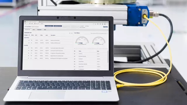
                            Visualization, diagnosis and optimization
                            • Meaningful visualization images with extensive diagnostic capabilities.
                            • All digital and analog input and output signals can be directly displayed.
                            • All output signals can be “forced”.
                            • All input signals can be “simulated”.
                            • The operating conditions of all controllers and limiters are visualized in detail.
                            • The fault monitoring system displays status, warning and alarm messages in a clear format with time stamp.
                            • Operating personnel can conduct extensive diagnoses quickly and without external support.
                            • Process sequences and process faults in your plant can be tracked in a very short time and in a targeted manner.
                            • All of this increases system availability, product quality, and last but not least, the productivity of the entire plant.
                            • Web visualization via Ethernet (LAN) and specified web browser.
                            • The complete visualization can be accessed with standard hardware and software.
                            • Several devices can access TurCon visualization simultaneously.
                            • There are no additional licensing costs to access TurCon visualization.
                            • You use the visualization without special client software and you do not need “admin rights” on your PC.
                            • 15 inch TFT-LCD control panel with intuitive touchscreen operator interface.
                            • The HMI interface is user friendly and modern.
                            • All parameters can be adjusted on site and relevant process values visualized.
                            • Operating personnel can be trained very quickly in the use of the system.
                            • You have quick and informative process visualization and monitoring on site.
                            • RemoteView & Control via LAN using a standard PC with specified browser or optional 15” touch panel.
                            • All operating, setting and monitoring functions can be executed in the same way as on the standard control panel.
                            • You have an additional, inexpensive HMI interface at another location.
                            • A large-scale visualization, e.g. during commissioning or for monitoring purposes, can be realized quickly and easily.
                            • Integrated tool for controller optimization during operation without significant disruption to the process.
                            • The control loops and their control accuracy can be quickly optimized.
                            • You save costs thanks to shorter commissioning time.
                            • You quickly reach high process quality.
                            • Simulation option available for all controller functions during the factory acceptance test (FAT) and before commissioning.
                            • The basic accuracy of the configuration and parameter-setting of the turbine controller can be effectively checked and optimized if necessary before the commissioning process as such.
                            • A preliminary simulation facilitates commissioning and cuts commissioning time.
                            • You therefore minimize the risk of damage due to incorrect parameters.
                            • RemoteAccess & Control via VPN tunnel (optional).
                            • Voith can provide simple and fast support.
                            • You get a fast and cost-effective analysis of the behavior of the system.
                            Hardware, software and redundancy
                            • Modular structure with proven standard hardware suitable for industrial use.
                            • Scalable hardware redundancy for fault-tolerant systems.
                            • The components of the control system are ideally matched to one another.
                            • The controller is extremely flexible and suitable for all steam turbine and compressor applications.
                            • Your control system offers a high level of operational reliability and is consistently easy to maintain.
                            • The controller is ideally suited for both new builds and upgrades to existing systems.
                            • Smart redundancy concept: 2-channel CPU with 2-channel input/output units.
                            • Continuous monitoring of both channels.
                            • Up to 3 inputs for each process value with 2oo3 (two out of three) logic.
                            • Redundant outputs with self-monitoring function, specifically for the actuators.
                            • The failure of one controller unit will not cause the turbine or compressor to shut down.
                            • Controller components can be replaced during operation.
                            • Your entire plant has a high level of productivity.
                            • The high reliability and availability of the controller ensures long operating intervals in accordance with predefined maintenance schedules.
                            • Watchdog monitoring.
                            • I/O malfunctions can be detected in real time.
                            • You avoid system failures and the consequences caused by incorrect input/output status.
                            • Scalable software functionality for all customer requirements.
                            • Proven and reliable software algorithms for the control and regulation of turbomachinery.
                            • Existing software routines can be easily adapted to customer requirements.
                            • High software quality forms the basis for reliability, efficiency, safety and ease of maintenance.
                            • Short development cycles and low development costs are easy on your budget.
                            • The commissioning of the control system takes little time and effort.
                            • Direct control of all HP, MP and LP valve actuators.
                            • Linearization of valve characteristics via individually configurable control variables.
                            • In the case of turbines with more than one HP, MP or LP control valve, there is no need to adjust the valves mechanically using a camshaft.
                            • Fewer mechanical parts means you have lower maintenance costs.
                            • In the case of turbines with more than one HP, MP or LP control valve, no separate electronic valve coordinator (split range) is necessary.
                            • Fewer electronic components reduce the complexity of the system and improve its reliability, while you gain higher system availability.
                            • The commissioning effort is reduced, which saves significant costs.
                            • The steam turbine control valves can be actuated flexibly.
                            • You are flexible in the design of the process.
                            • Multilevel password protection.
                            • The operation of the controller is well protected.
                            • Your turbine control system is secure and protected from unauthorized interventions.


                            Typical applications

                            • Control of steam turbines that drive generators
                            • Control of steam turbines that drive compressors, pumps, fans and other driven machines
                            • Control of compressor trains
                            • Upgrade/retrofit/modernization of mechanical-hydraulic steam turbine controllers
                            • Upgrade/retrofit/modernization of analog steam turbine controllers, in particular:
                              • Voith TurCon A
                              • Siemens/KKK SC800
                              • MAN/GHH Turbolog EKU
                              • Dresser Nadrowski/M+M/AEG Kanis/ABB CTn, CTp, and CTf
                            • Upgrade of outdated digital steam turbine and compressor controllers
                            • Upgrade of non-redundant steam turbine and compressor controllers
                            • Upgrade of Woodward 505 and Woodward 505E steam turbine controllers

                            TurCon DTe impressions


                            io.Con – the operating system for smart actuators

                              Digital, intelligent and robust as ever. Now a new generation of actuators is entering the stage.

                              Digital, intelligent and robust as ever. Now a new generation of actuators is entering the stage.

                              Digital electronics with microcontroller control the actuators and offer many innovative functions and diagnostic options.
                              More about io.Con

                              Application areas

                                Applications for Voith actuators and control systems

                                How can we help you?

                                  J.M. Voith SE & Co. KG | DSG

                                  Actuators and Governors

                                  Voithstr. 1 74564 Crailsheim Germany


                                  t +49 7951 32-470

                                  Voith Service – How can we help you?

                                    Why use Voith Service?
                                    Why use Voith Service?

                                    • Everything from a single source: development, design, production – and service!
                                    • Decades of product experience as an original equipment manufacturer and service provider
                                    • Fast and smooth cooperation and best service thanks to a worldwide network of service locations
                                    • Long-term partnership and planning security are guaranteed due to longstanding corporate stability

                                    To our entire service portfolio Voith Turbo Webshop

                                    Publications

                                      RIGHT OFFCANVAS AREA