
Speed control you can rely on
You can count on the proven reliability of 99.98% when integrating a geared variable speed coupling into your application.
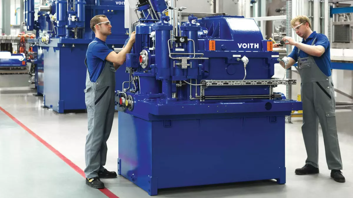
Suitable for power applications of up to 30 MW and output speeds of up to 20,000 rpm, these units are typically found in thermal power plants and oil and gas industry applications. The indicated applications usually combine a standard motor with a geared variable speed coupling to ensure precise and accurate speed control.
3 in 1
Three in one function:
Speed control – Transmission for speed conversion – Integrated oil supply
99.98%
Unbeatable reliability of 99.98%
10,000
Longest international track record with over 10,000 installed units
70 %
Compact – Minimal footprint – Saves up to 70% space
Simple design
Simple mechanical and robust design for indoor and outdoor installation
How a geared variable speed drive works
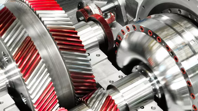
This compact unit combines a hydrodynamic variable speed coupling and a mechanical gearbox. The gear stage is designed for the initial increase or decrease of the input driver speed while the variable speed coupling varies the speed of the driven machine within the required range.
Our portfolio
|
|
R..K..M
Type R..K..M – The standard

R..K..M sectional diagram
Function – High power density at medium speeds
- The input speed is converted up to a higher speed.
- When the motor starts, the hydrodynamic variable speed coupling is empty. The drive motor and the driven machine are decoupled. The motor starts up under virtually no-load conditions.
- The hydrodynamic coupling is filled after the motor has started and smoothly accelerates the driven machine to the minimum speed.
- The speed of the driven machine is controlled by the stepless positioning of the scoop tube.
- The scoop tube changes the oil filling in the variable speed coupling, thus changing the power transmission.
- Using the hydrodynamic principle, a fluid flow transmits the power wear-free from the pump wheel to the turbine wheel.
- The turbine wheel is connected to the driven machine via the output shaft.
- The integrated oil system fills the hydrodynamic variable speed coupling with the working oil. At the same time, the geared variable speed coupling, the drive motor, and the driven machine are supplied with lube oil.
R..GS..M
Type R..GS..M – The fast one

R..GS..M sectional diagram
Function – High output speeds
- The R..GS..M geared variable speed coupling is used in conjunction with 2-pole standard motors. It converts the fast input speed into an even higher output speed.
- The design of the R..GS..M type is based on the R..K..M geared variable speed coupling. The hydrodynamic variable speed coupling is arranged infront the gear stage.
R..A
Type R..A – The slow one

R..A sectional diagram
Function – Low output speeds
- The gear stage converts the motor speed into a lower output speed.
- Mounting a hydrodynamic brake is possible as an option.
R..B
Type R..B – Turns the corner

R..B sectional diagram
Function – Low output speeds
- The R..B geared variable speed coupling converts the motor speed to a lower output speed, just like the R..A type.
- A bevel gear is located at the output of the hydrodynamic variable speed coupling.
- The driven machine is arranged at a 90° angle from the drive motor.
- Mounting a hydrodynamic brake is possible as an option.
Special features and characteristics
Main features include:
- Double helical parallel shaft gear
- Journal bearings
- An integrated lube oil supply for motor and driven machine
Optional:
- Explosion-proof
- AGMA 6011 or API 613 compliance
Key technical data
| Rated power | 1 - 30 MW |
| Input speed | 1,500, 1,800, 3,000 or 3,600 rpm |
| Rated output speed | Up to 20,000 rpm |
| Speed range | 25% - 100% |
References

Speed regulation with a geared variable speed drive for a boiler feed pump in a lignite-fired power plant in Thailand.

Speed regulation of a water injection pump for oil extraction in Oman relies on Voith’s geared variable speed couplings.

Our couplings control the speed of the boiler feed pumps in one of Europe´s largest lignite-fired power plants.